
Piezoceramics testing for crack detection
TRZ® Analyzer and PiezoHolder application
Objectives and applications
Piezoelectric ceramics are fragile and sensitive components that may present internal cracks undetectable to a visual inspection. Ceramics presenting cracks, even if internal and invisible, must be discarded to avoid the premature fault of ultrasonic transducers and converter in which they are mounted, and the resulting losses from repairs and technical assistance.
This white paper presents a practical and effective methodology for detecting cracks in piezoelectric ceramics used in ultrasonic transducers and converters. This approach is a variation of the acoustic resonant inspection (ASTM–E2001), which obtains the frequency spectrum through impedance analysis. Manufacturers and final users of piezoelectric ceramics, ultrasonic transducers and converters may apply this methodology in the following cases:
- Quality control in manufacturing piezoelectric ceramics;
- Receipt inspection of new piezoelectric ceramic pieces;
- Verification of ceramics recovered from transducers and converters reproved in the production line;
- Verification of ceramics recovered from damaged and dismantled transducers and converters.
Introduction
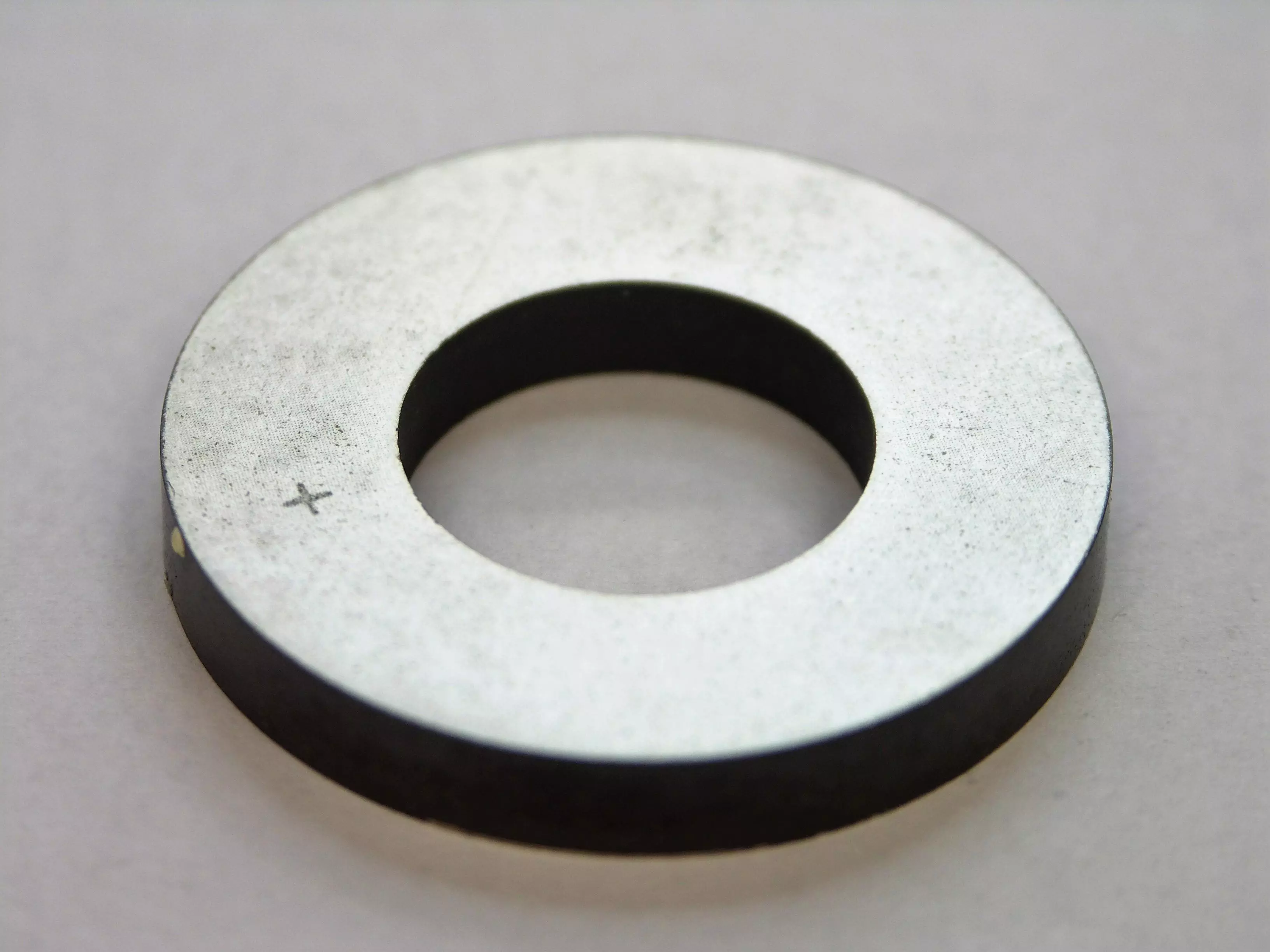
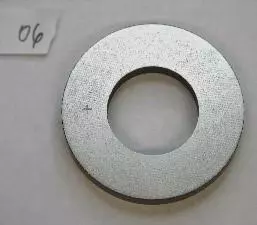
Figure 1 shows a typical piezoelectric ceramic of 20 kHz converters for ultrasonic welding. Its dimensions are 38.1 x 19.1 x 5.15 mm and its material is the PZT-8. There are metallic electrodes on its two flat faces for the application of electrical voltage and on one of the faces shows the polarity mark (the positive is marked with a “+” and/ or a dot “•”, which may be also on the side). These ceramics are made by pressing and sintering the powder Lead Zirconate Titanate (PZT). PZT can be found under diverse variations and denominations, confirm the correct application and specification with the manufacturer.

Piezoelectric ceramics are the main element of ultrasonic transducers and converters and are responsible for the electric energy conversion into ultrasonic waves and vice-versa through the piezoelectric effect. Cracks - even if internal and dimensionally small - trigger heating, loss of productivity and frequency variations of transducers or converters.
The presence of cracks on the piezoelectric ceramic compromises the symmetry of mechanical stress and deformation with the vibration and causes the concentration of stress, leading to the growth of the crack in a vicious cycle and, eventually, to a complete rupture. Figure 2 shows the comparison between an intact ceramic ring deformation and a cracked ring, both in the fundamental radial vibration mode. Figure 3 presents an illustrative sequence of the growth of an internal crack until the rupture of the piece.
 b)
b)


Cracks may occur during:
- The manufacture of ceramic pieces because of the unequal distribution of power on pressing molds;
- The assembly of transducers or converters because of irregularities on the surface or excessive prestress (>50 MPa) or abrupt tightening (>5 MPa/s);
- The transducer or converter use because of fatigue, overload, loss of pre-stress, overheating or electric arching;
- The transport or handling because of mechanical shocks and falls.
The number of new ceramics presenting cracks may be superior to 3%, depending on their origin and the rigorousness of the manufacturer quality control. This percentage is relevant because only one ceramic with a crack is enough to compromise the ultrasonic transducer or converter.
Foundations
Every rigid body presents resonant frequencies associated with vibration modes. Piezoelectric ceramics shaped liked rings and disks are mainly associated with the radial and thickness vibration modes.
Figure 4 shows the typical impedance curve of three common and intact commercial piezoelectric ceramic pieces. Note that the bigger the ceramics, the lower are their frequencies. In the case of the bigger ring, measuring 50.8 x 19.1 x 5 mm, there is a second resonance that corresponds to a harmonic fundamental radial mode. Other commercial ceramics with similar dimensions shaped like rings present the same pattern.

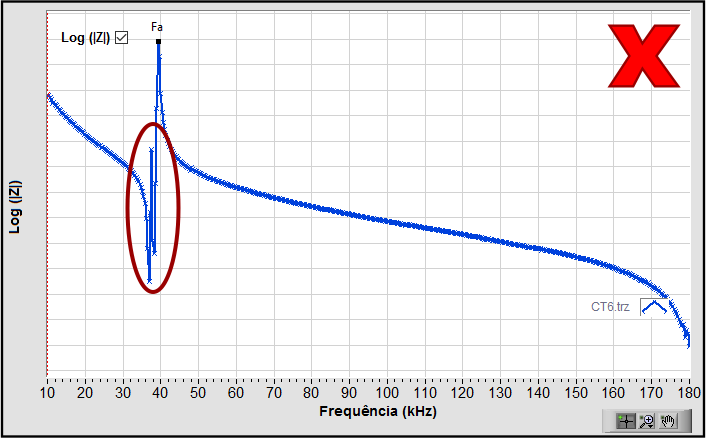
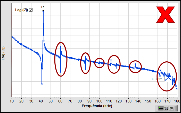
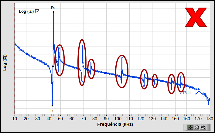
The presence of cracks allows the occurrence of additional vibration and resonance modes, which are detectable by employing the TRZ® Analyzer and Software. Figure 5 and 6 present the impedance spectroscopies (impedance module as a function of frequency/curve |Z(f)|) of two similar piezoelectric ceramics, being one of them intact (Figure 5) and the other cracked (Figure 6).
Judging the result is simple and straightforward: there must be no multiple resonances (from additional vibration modes allowed by the crack), and there must be a maximum of two vibration modes in the frequency range from 10 to 180 kHz for ceramics with the external diameter measuring between 20 and 60 mm. The intact ceramic (Figure 5) presents only one vibration mode (highlighted in blue), while the cracked ceramic (Figure 6) presents several additional vibration modes, besides the main vibration mode.


Methodology
The test methodology for crack detection in piezoelectric ceramics is very simple and can be easily carried by following the step-by-step instructions below:
Step 1 – Use the TRZ® Analyzer and the PiezoHolder
Use the TRZ® Analyzer with the TRZ® Software (7.0 version or higher) and the PiezoHolder (Figure 7). Select the option “Piezos” on the Software (Figure 8). Under this pre-configuration, the TRZ® Analyzer and Software will perform a sweep between 10 and 200 kHz.


Step 2 – Insert the ceramic piece into the PiezoHolder
Insert the piezoelectric ceramic piece into the PiezoHolder (Figure 9). This accessory is capable of holding disks and rings with thickness between 0 and 19 mm, and diameter between 15 and 100 mm. The polarity is not relevant.

Step 3 – Carry out the measurement and analysis
Take the measurement by clicking on “Play” (Figure 10) or using the shortcut command Ctrl-N. Then, check if the obtained curve is subtle or if it has disturbances of low amplitude (see figures 5 and 6). If spurious modes are detected, the piezoelectric ceramic is cracked and must be discarded. The presence of cracks may be confirmed by non-destructive ultrasonic testing (pulse-echo).

Important observation: this methodology is not sensitive to chips on the edges of the ceramic pieces. Ceramics presenting this kind of defect must be discarded even if they are not cracked.
Examples
Table 1 shows the characterization results of a new and intact ceramic piece, of a new but internally cracked ceramic piece, of a used and internally cracked ceramic piece, and finally of a new ceramic piece presenting an unknown defect. Note that the pattern of additional resonances indicating the presence of crack varies.The visual inspection of the ceramics were carried out by using an 8x magnifier. Before the visual inspection, the surfaces of the used ceramics were sanded with a 1500 sandpaper and cleaned with a solvent for removing dirtiness.
Table 1 – Example of tests involving intact, internally cracked or defected ceramics.| Description | Curve obtained with the TRZ® Analyzer | Observations |
New and intact ceramic
|
|
This new ceramic was approved because there is no additional resonances and because of a well-defined main resonance. Curiosity: the ATCP Physical Engineering logo was inspired by the shape of this wave pattern. |
| New ceramic with internal crack
|
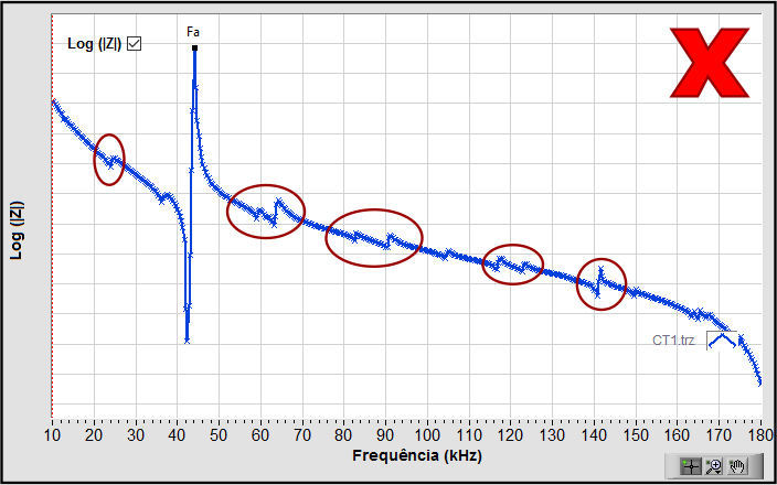
|
This new ceramic was not approved because multiple additional resonances were detected. The existence of crack was confirmed by the non-destructive ultrasonic testing for the detection of discontinuities. |
Used ceramic with internal crack
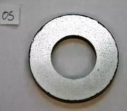
|
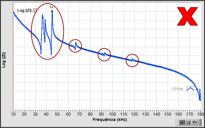
|
This used ceramic was not approved because there are multiple additional resonances besides disturbances on the main resonance. The existence of crack was confirmed by the non-destructive ultrasonic testing for the detection of discontinuities. |
New ceramic presenting a unknown defect
|
|
This new ceramic was not approved because there is a disturbance on the main resonance, however it was not possible to confirm that it has an internal crack by non-destructive ultrasonic testing. The defect that generated this disturbance may be a density inhomogeneity of the pressed material. |
These cases present more accentuated additional re sonances, but they are not too different from the additional resonances observed in internally cracked ceramics (refer to Table 1 curves).
Table 2 – Example of tests involving used and visibly cracked ceramic and fractured ceramic (extreme situations in which the visual inspection would have been enough).| Description | Curve obtained with the TRZ® Analyzer | Notes |
| Used and visibly cracked ceramic
|
|
This used ceramic was not approved because it shows a visible crack, besides multiple additional resonances. |
| Ruptured used ceramic missing a segment
|
|
The presentation of the test for this fractured ceramic missing a segment aims to illustrate the application of the methodology in an extreme condition. |
Piezoelectric ceramics recovery and reuse
The fracture of ceramics is the main cause for faults of transducers and converters. Figure 11 exemplifies a 35 kHz damaged converter, highlighting the ruptured piezoelectric ceramic piece. However, not all ceramics of damaged transducers are necessarily compromised. On the contrary, some may be recovered to reduce maintenance costs, mainly when it comes to premature faults during manufacturing tests. For that, it is necessary to use a methodology that guarantees the inexistence of cracks in the ceramics that will be reused.

For transducers and converters that have failed after long period of use, it is quite probable that the intact ceramics may present a reduced lifespan and occasional changes to the piezoelectric constants. However, that does not stop these ceramics from being refurbished.
To recover used ceramics, besides testing them for crack detection, it is necessary to remove the insulating varnish or epoxy resin that might be occasionally present on the sides of piece. It is also advisable to lightly sand the ceramic electrodes using a 2500-grain or superior abrasive pad to eliminate marks and dirtiness. It is important to be careful to avoid excessive sanding and the consequent removal of electrodes.
Learn more about the TRZ® Analyzer