FAQ: We bought the TRZ® Analyzer, but we are not used to the information of the measurement results. What are the Fa, Za, Fr, Zr and Fc parameters for?

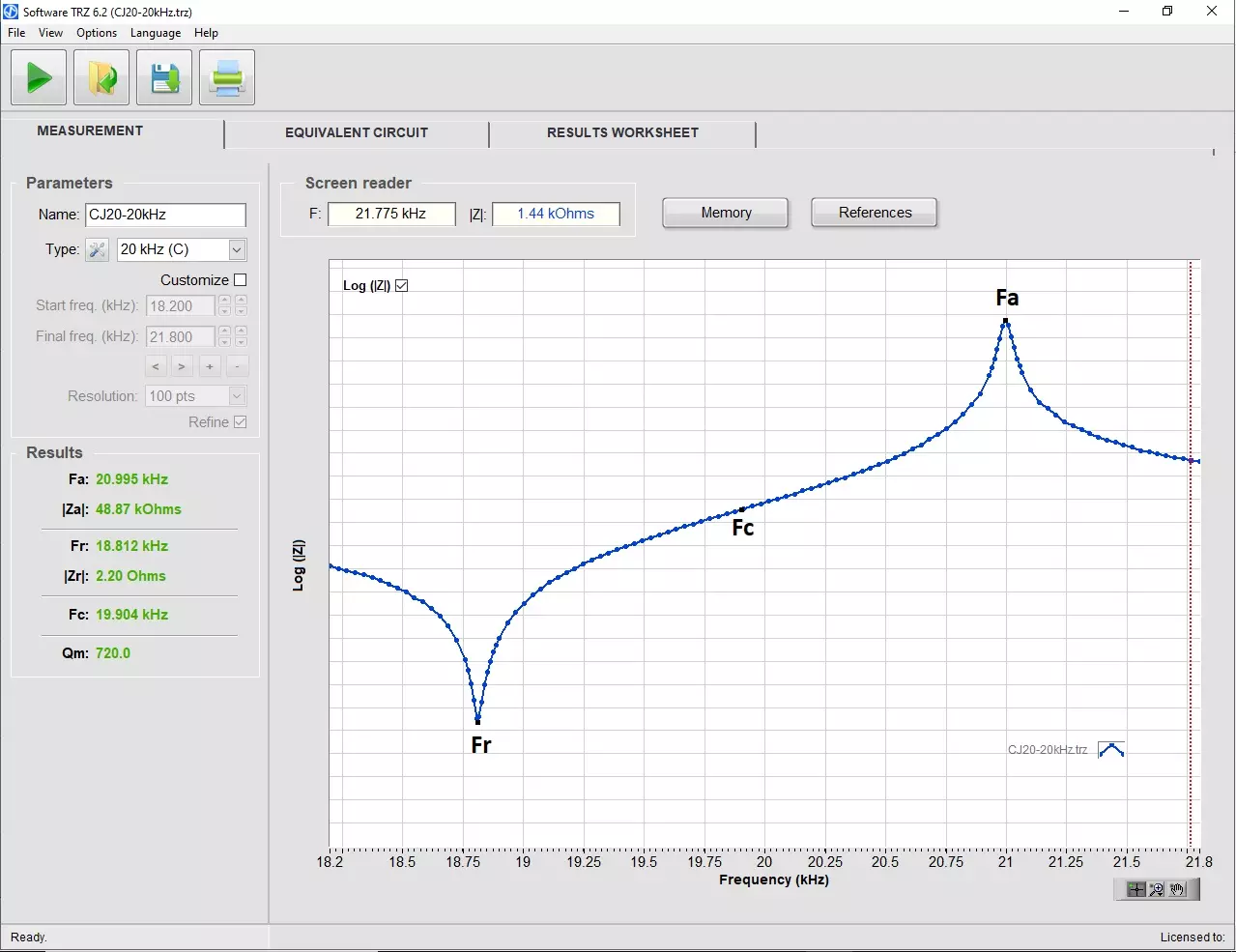
Impedance curve of a new ultrasonic welding converter. Curve measured by the TRZ® Analyzer.
Fa is the antiresonance frequency (colloquial designation) or parallel-frequency (precise designation). At Fa, the electrical impedance modulus is maximum, thus the current demanded from the generator is minimum. The impedance at Fa is named Za (impedance at antiresonance frequency). To drive at Fa is a typical choice when dealing with ultrasonic welding equipment.
Fr is the resonance frequency (colloquial designation) or series-frequency (precise designation). At Fr, the electrical impedance modulus is minimum, thus the current demanded from the generator is maximum. The impedance at Fr is named Zr (impedance at resonance frequency). To drive at Fr is a typical choice when dealing with ultrasonic cleaning equipment.
Fc is the average between Fa and Fr.
The figure shows an example of modulus of impedance curve highlighting the Fr, Fa and Fc for a brand-new ultrasonic welding converter. Note: ATCP Physical Engineering logo was inspired on this pattern, typical of ultrasonic transducers and piezoelectric devices.
With proper tuning, an ultrasonic transducer is able to operate at any frequency between Fr and Fa, or in their vicinity.
Learn more about testing converters and acoustic stacks.
