
Horn tuning & Stack testing
TRZ® Analyzer applications
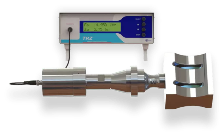
TRZ® Analyzer main applications are horns and ultrasonic parts tuning, ultrasonic welding stacks maintenance, converters repair and transducers quality control. It is also used in receipt inspection and in research and development.
Horns and sonotrodes tuning
Frequency tuning of ultrasonic horns and similar is required for new parts to compensate for elastic properties variations and milling tolerances. For used and worn horns, tuning is required to compensate dimensional changes in order to extend their lifespan.
In the case of ultrasonic welding and cutting equipment, the horn frequency should match the booster and converter ones for vibration efficiency and spare parts compatibility. This is the same for medical and dental equipment, such as ultrasonic scalpels, scissors and scalers, ultrasonic polishing and ultrasonic grinding equipment.


Dimensional changes for increasing and decreasing the frequency.
The basic dimensional changes for horn and ultrasonic parts tuning are length reduction, step/radius position shift and slots widening. As illustrated above, the frequency will increase when you reduce the part length and will decrease when you move the step/radius position or widen slots in steeped horns. In both cases you need to remove material, however, length changes are straightforward to execute and the frequency sensitivity is much higher.

The tuning process consists in changing the ultrasonic part dimensions by employing machine tools (lathe, milling and grinding) combined with TRZ® Analyzer measurements until reach the target frequency. Each dimension change should be small and preceded by TRZ® Analyzer testing. To be measured, the horn must be coupled to a converter and booster, as used at the production floor.

Frequency increase with length decrease along a 15 kHz block type horn tuning process. The target frequency was 15.000 kHz ±0.050 and the final frequency 14.950 kHz. The sensitiveness was ≈90 Hz/mm (2.3 Hz/mil).
The standard operation to tune a horn is to reduce its length because it is the easiest dimension to change and the frequency is more sensitive on this direction (≈160 Hz/mm for 20 kHz parts). A new horn or replica is usually machined lengthier to later tuning with length reduction, +4 mm (≈160 mil) is enough for 20 kHz horns. The change of radius position and slots widening are limited to horns reconditioning; wear and facings reduce the length, thus increasing the frequency, which can be corrected to some extent.
| Frequency | Typical frequency sensitivity for length change | Typical length | Typical excess (≈3% of typ. length) |
| 15 kHz | 90 Hz/mm (≈ 2 Hz/mil) | 170 mm (≈ 6” 3/4) | 5.0 mm (≈ 200 mil) |
| 20 kHz | 160 Hz/mm (≈ 4 Hz/mil) | 128 mm (≈ 5”) | 4.0 mm (≈ 160 mil) |
| 30 kHz | 360 Hz/mm (≈ 9 Hz/mil) | 85 mm (≈ 3” 3/8) | 2.5 mm (≈ 100 mil) |
| 35 kHz | 480 Hz/mm (≈ 12 Hz/mil) | 73 mm (≈ 2” 7/8) | 2.2 mm (≈ 85 mil) |
| 40 kHz | 630 Hz/mm (≈ 16 Hz/mil) | 64 mm (≈ 2” 1/2) | 2.0 mm (≈ 80 mil) |
It is worth to mention that is not possible to refurbish a cracked horn or booster, it must be replaced immediately to avoid damaging other parts or the generator. Annoyingly high pitch sound is typical of cracked parts, it is possible to confirm the crack presence and identify its location by dye penetrant inspection.
Ultrasonic welding stacks testing
To identify which one of the stack elements is not working properly, a progressive test should be performed: firstly, test the converter alone; secondly test the converter and the booster coupled (converter+booster); lastly the complete stack (converter+booster+horn). At each step, specific acceptance criteria should be applied for frequencies, frequency range, mechanical quality factor and impedances. Where there is not a booster, only “converter+horn”, use the “converter+booster” criteria.
| Converter alone | Converter+booster | Converter+booster+horn | |
| Mechanical quality factor (Qm) | ≥ 250 | ≥ 700 | ≥ 1000 |
| Frequency range [Fr-Fa] | Should include the stack nominal frequency | Should be within the converter frequency range | - |
| Operational frequency (usually Fa) | - | - | Should be equal to or tighter than the stack nominal frequency ±0.5% |
Over the years we learned the typical deviations of malfunctioning ultrasonic stacks parts and condensed this knowledge within general guidelines and acceptance criteria. The guidelines have been summarized on the table above and the criteria programed on the TRZ® Software.
There are many ways manufacturers can align the stack parts frequencies and drive it, making it impossible to define specific guide lines and criteria that would be perfect to all of them at the same time. In spite of that, the guidelines and criteria we offer herein and within the TRZ® Software are a good start that can be later refined by testing new parts and/or by requesting further specifications and tolerances from the manufacturers.
Before running tests, ensure that the stack parts mating surfaces are flat, parallel and clean. A light coat of high temperature grease or a Mylar® washer on the mating surfaces is recommended. Any mating surface in bad condition should be reconditioned, because poor mating surfaces compromise both mechanical quality factor (Qm) and performance. Likewise, clean and check the studs and threads.
Testing converters (converter alone)
The mechanical quality factor (Qm) of converters must be equal to or higher than 250 regardless of the frequency, power or manufacturer. This number is a general guideline based on our practical experience. Qm is a parameter proportional to the part efficiency in vibrating. For power applications, the higher the Qm, the better the part. One can understand the Qm as how many times the device oscillates after power is turned off (this is a rough approximation for illustration purpose only); a converter that oscillates 800 times (Qm=800) vibrates more efficiently and dissipates a lower energy fraction than one which oscillates 250 times (Qm=250).
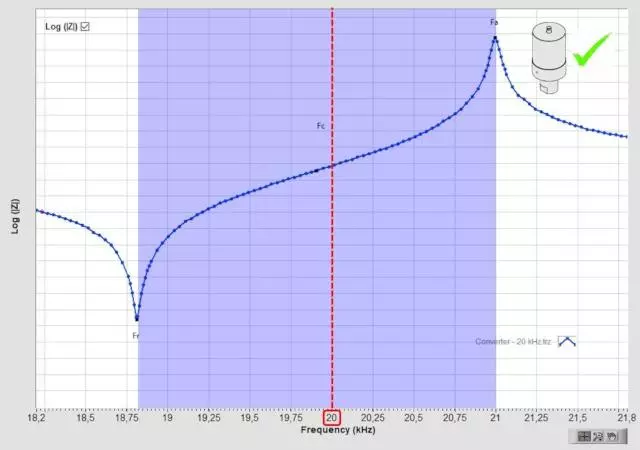
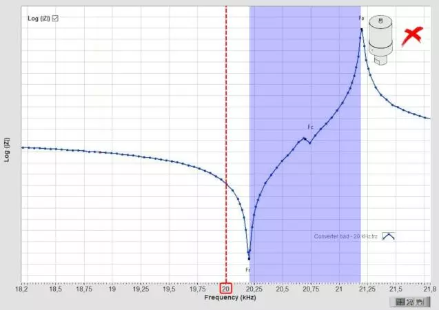
The converter frequency range [Fr-Fa]C should contain the stack nominal frequency. In the first figure above, the stack operational frequency (20 kHz) is within the blue region, indicating the converter passed with regard to this criterion. In the second figure, the stack operational frequency (20 kHz) is out of the blue region, indicating the converter frequency is out of tolerance (too high). The operational frequency range may be anywhere between the converter Fr and Fa, however, the most common is to be close to Fr. A stack with a high or low frequency converter may work and be acceptable, but with lower efficiency and higher heating than a proper tuned one.
The converter frequency range [Fr-Fa]C should contain the stack nominal frequency. In the first figure above, the stack operational frequency (20 kHz) is within the blue region, indicating the converter is ok with regard to this criterion. In the second figure, the stack operational frequency (20 kHz) is out of the blue region, indicating the high frequency of the converter. The operational frequency range may be anywhere between the converter Fr and Fa, however, the most common frequency should be close to Fr. A stack with a high or low frequency converter may work and be acceptable, but with lower efficiency and higher heating than a proper tuned one.
Other criteria are applied by the TRZ® Software in relation to the frequencies and respective impedances, however they are not strict because the frequencies and impedances of converters vary greatly with the device maximum power and from one manufacturer to another (users may refine the criteria at their own).
Testing boosters (converter+booster)
If the converter fails on the previous step, you have found the problem or at least one of them. If the converter passed, the problem is somewhere else and you can move to the next step by testing the booster. To test the booster, you need to couple it to a converter in good conditions (it can be the stack's own) with the proper torque and procedures recommended by the manufacturer.
The “converter+booster” mechanical quality factor (Qm) must be equal to or higher than 700 regardless of the frequency, power or manufacturer. This number is a general guideline based on our practical experience. We recommend to also test the “converter+booster” clamped in the welding machine mount for the mechanical quality factor (Qm). Sometimes the booster problem is a damaged O-Rings cushion, what may be detectable only if the booster is clamped in the mount (if the O-Rings cushion is damaged, the mechanical quality factor will decrease considerably after clamping). This test is also important during developments to check if the booster nodal line is coinciding with the clamping region.
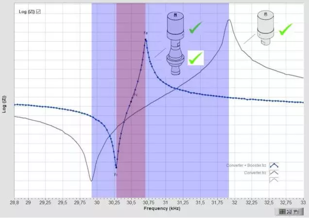
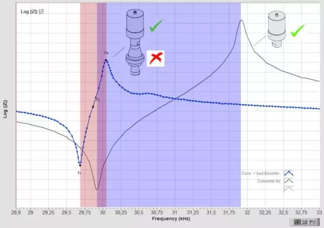
The “converter+booster” frequency range [Fr-Fa]C+B should be within the “converter alone” frequency range [Fr-Fa]C (blue region), as exemplified on the first image above (the “converter+booster” range may be anywhere inside the converter range). The second image above illustrates a case of low frequency booster where the [Fr-Fa]C+B is not within the “converter alone” frequency range [Fr-Fa]C (the red box). The judgment is graphical/visual.
Other criteria are applied by the TRZ® Software in relation to frequencies and their respective impedances, however they are not strict because the frequencies and impedances of converters and boosters varies greatly with the device maximum power and from one manufacturer to another (users may and should perform refinement where possible).
Testing horns / stacks (converter+booster+horn)
If the “converter+booster” fails in the previous step, the problem is the booster. If the “converter+booster” passed, the problem almost certainly is the horn and you can move to the next step by testing the complete stack. Couple the horn to the booster with the proper torque and procedures recommended by the manufacturer.
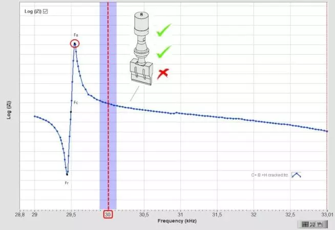
The stack mechanical quality factor (Qm) should be equal to or higher than 1000, regardless of the frequency and power. The Qm equal to or higher 1000 is a general guidance based on our practical experience (we have never tested an acoustic stack working properly with Qm lower than 1000). When the horn is cracked, the stack mechanical quality factor decreases considerably.
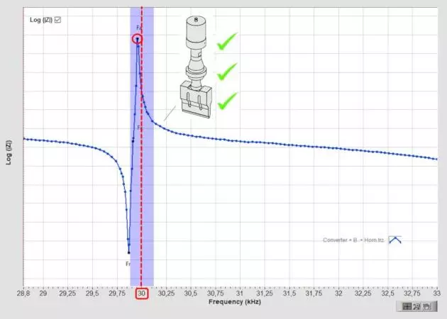
The operational frequency should be equal to the nominal one plus minus 0.5% (e.g., 20.00 kHz ±100 Hz). The frequency tolerance may be tighter for high-grade equipment (±0.25 % is usual for high-end equipment). In most cases the operational frequency is the antiresonance frequency (Fa), a few brands drive welding equipment at the resonance frequency (Fr) or between resonance and antiresonance frequencies; you can find it out by measuring the machine with the SonicSniffer® non-contact frequency meter.
You can have bad stacks at the right frequency. It happens, for instance, when you have a wear (that increase the frequency) and poor interfaces (that decrease the frequency) simultaneously. In these cases, you will detect the problem by looking at the mechanical quality factor Qm, which should be higher than 1000.
In an acoustic stack, or any resonant compound device, each part acts like a band pass filter and, if their frequencies are not aligned, the stack will have low efficiency. Low efficiency comes with overheating, overloading the generator and faster fatigue, making horn poor tuning the root of many problems in the power ultrasonic systems. Note: The maximum recommended operating temperature is 45 °C (≈110 °F).
Quality control of ultrasonic transducers
TRZ® Analyzer is able to perform the quality control of converters, ultrasonic parts and medical transducers by the testing their frequencies, impedances and mechanical quality factor. To pass, these parameters must be within the acceptance criteria. The TRZ® Analyzer is also able to generate pdf test report and export test results to spreadsheet for traceability.
The acceptance criteria are usually based on averages and standard deviations of reference parts. If necessary, the ATCP team will assist the customer on the acceptance criteria determination.
Receipt inspection
At receipt inspection, deviations indicate quality issues and must be evaluated to avoid further maintenance problems instead of solve them. A horn out of frequency tolerance may operate, but with low performance, overheating issues and reduced lifespan, besides the risk of damaging the generator and other stack elements.
It can be surprising how many new parts with problems our customers detect and avoid acceptance after adopting the receipt inspection with the TRZ® Analyzer testing.
Converters repairing
TRZ® Analyzer is able to test refurbished converters and transducers by applying pre-configured acceptance criteria for frequencies, impedances and the mechanical quality factor. For repairing, it is necessary to replace the damaged piezoelectric ceramics with equivalent ones (same material and dimensions) and inspect the metallic elements for cracks. Typically, cleaning transducers employ PZT-4 material and ultrasonic welding converters PZT-8. The thickness is especially critical and must be the same with a tolerance of ±0.01 mm, otherwise it will change the device frequency. Capacitance is also important; however, it is a parameter that piezo manufacturers do not have much control over. Consequently, it may be necessary to tune the power generator to compensate capacitance variations of the ceramics (if the capacitance is the same, this procedure is avoided). When reassembling a converter, pay attention to the piezoceramics positioning with regards polarity and apply the ideal prestress by bolt preloading. For more information on optimal prestress, please visit the following page: https://www.atcp-ndt.com/en/essentials/prestress-technology.html
Products development
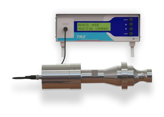
TRZ® Analyzer is a dedicated impedance analyzer capable of testing any ultrasonic transducer or piezoelectric device for frequency, impedance and the mechanical quality factor in the range from 1 to 200 kHz. In the context of product development, the TRZ® Analyzer is especially useful in tuning prototypes and optimizing the nodal line. To test whether the nodal line is coincident with the clamping position, just measure and compare the mechanical quality factor Qm in free and clamped conditions. The smaller the fall in Qm caused by the clamping, the better the coincidence of the nodal line with the clamping region. The optimization of the nodal line can be performed by mirroring the front and rear regions of the transducer with respect to the nodal line, if the frequency of the mirrored transducers coincides, then the transducer is balanced and the nodal point in the right place. Otherwise, the mirrored side with higher frequency than the transducer should be stretched, and the side with lower frequency shortened. For more information on nodal line optimization, contact us.
Learn more about the TRZ® Analyzer