FAQ: I have a question about the parameter Qm. No matter how much I searched I could not understand exactly what that is. It's called mechanical quality factor, but what exactly does it tell me about the device I measure? If a device has Qm = 500, is it worse or better than one with Qm = 700? Mr. F.S. How is this Qm value determined? Is it the higher delta impedance between resonant frequency and anti-resonant frequency, or the higher value for Qm? Mr. K.T.Y.

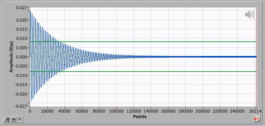
The vibration decay of an ultrasonic horn after the excitation ceases is proportional to Qm.
Qm is a parameter proportional to the device under test efficiency in vibrating, and inversely proportional to its damping or internal losses. For power applications, the higher the Qm, the better the device. The Qm value is approximately the number of times the device oscillates at no-load condition after excitation ceases. For a car, Qm would roughly be equal to length (measured in meters) it is able to move on a flat road after fuel is over.
Everything that interferes with the device efficiency when vibrating affects the Qm, for example, its joints condition, mechanical parallelism, alloy, piezoceramics quality and frequency matching between the acoustic stack elements. Cracks in piezoelectric ceramics or metallic masses sharply reduce Qm, which allows using this parameter to identify failures.
The knowledge of Qm is highly useful for maintenance and quality control of power ultrasonics because it is an absolute parameter, so it does not depend on the element under test frequency or power. In general, ultrasonic welding converters in good condition, and cleaning ultrasonic transducers, shall have Qm equal or greater than 250 regardless of power and frequency. The TRZ Software default criteria for ultrasonic welding device Qm minimum value are shown in the table below.
It is worth mentioning that TRZs’ criteria are standard values based on our field experience, it may be necessary to refine it depending on your case.
TRZ® Software default criteria for ultrasonic welding devices Qm minimum value.
| Device under test | Qm minimum |
| Converter/Transducer | 250 |
| Converter+Booster | 700 |
| Converter+Booster+Horn | 1000 |
To test an ultrasonic device or piezo element for Qm, it should be at no-load condition. Therefore, you need to support it in a nodal point, like the center of a disc for the radial mode, or in a nodal line, like a welding booster outer diameter. A ring is not the most proper geometry to test piezo elements for Qm.
With regards to the Qm calculation performed by TRZ® Software, it is equal to the average between the quality factor (Q) of the BDV circuit piezoelectric branch on the series and parallel configuration. The BDV circuit is calculated in the software tab “EQUIVALENTE CIRCUIT”. The formula for the Q-factor of the RLC piezoelectric branchs is Q = 1/R * √(L/C). The higher the delta impedance between Zr and Za, the higher the Qm. Furthermore, the shorter the spacing between Fr and Fa, the higher the Qm.
Learn more about testing converters and acoustic stacks.
